热销产品
IGBT模块尖峰电压测量及吸收电容规格(3)
Measuring capacitor RMS current
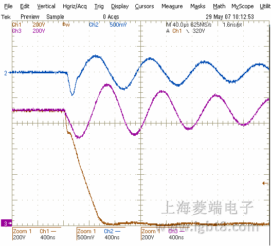
An alternating current is flowing in the capacitor after switching off IGBT and diode. When switching off IGBT, the current from the bus bar commutates into the snubber capacitor. This leads to a
positive peak current at the switching moment. This is followed by a damped oscillation between snubber capacitor and DC-link capacitor (Fig. 7).
When switching off the diode, the reverse recovery current will be “pulled out” of the snubber capacitor. This leads to a peak current in negative direction at the switching moment. Similar to switching off IGBT, a damped oscillation follows that can even be higher in amplitude than at IGBT switch off (Fig. 8).
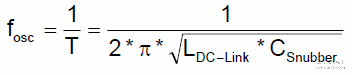
The frequency of the damped oscillation in both cases is determined by the bus bar parasitic inductance and the snubber capacitor value. Typically, the frequency is in the range of 100 kHz up to several MHz..
The oscillation leads to losses in the capacitor and consequently to self heating. The data sheet of the capacitor supplier gives the permissible load of the capacitor as RMS voltage or RMS current. Measurements and calculations must be carried out to check that the capacitor is not overloaded in the operating system.
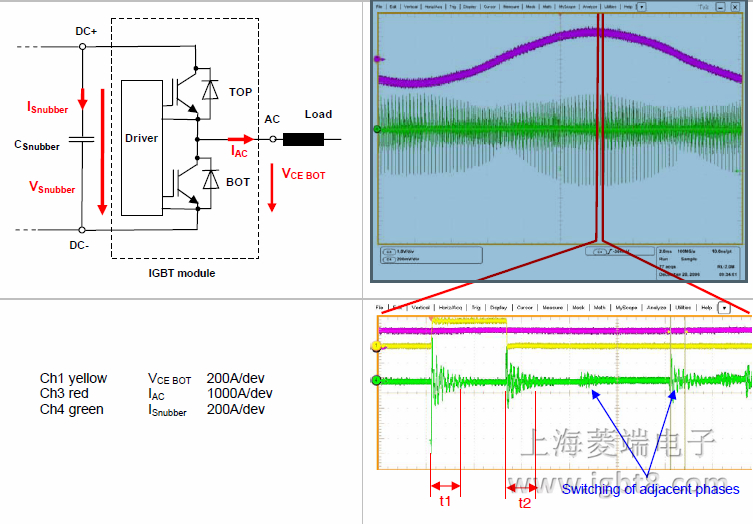
Measurement procedure
Current measurement carried out, for example, by a Rogowsky current transducer surrounding the capacitor leg produces good results. An AC-voltage measurement can be less accurate because of its low value in comparison to the high DC-voltage.
The RMS value can often not be calculated simply by using the “RMS measure” function of a modern digital oscilloscope over a whole period of inverter output frequency. The offset of the probes are too high in comparison to the low total RMS values to obtain accurate figures.
A practical approach is to measure the RMS value within the oscillation time at switch off of “BOT”-diode (t1) and “TOP”-IGBT (t2) (see Fig.9). These two parts are set according to the switching period (T =1/fsw) to calculate from this the total RMS value for the switching period. This has to be done for the whole sinusoidal waveform of a frequency converter. As a worst case consideration it can be done once at the maximum values of IRMS(t1) and IRMS(t2).
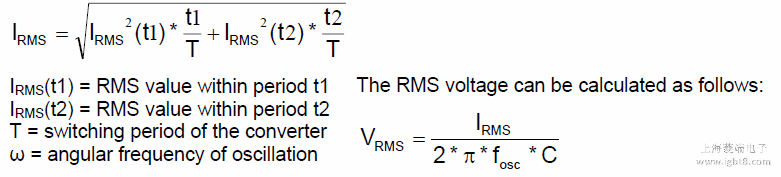
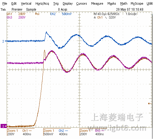
Fig. 7 Switching off IGBT