热销产品
IGBT参数测试IEC标准五-静态电压电流
6.3.1 IGBT Collector-emitter sustaining voltage (VCE*sus):IGBT集电极-发射极维持电压
6.3.1.1 目的
The purpose is to ensure that the collector-emitter sustaining voltage of an IGBT is not less than the maximum specified value VCE*sus under specified conditions.文章来源:http://www.igbt8.com/jc/172.html
6.3.1.2 测试电路 (see Figure 11)
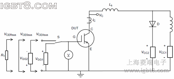
The IGBT is operated in a saturated condition under pulse operation.
Due to the inductance L, switching off the gate voltage causes the IGBT to be swept through a current-voltage cycle.
The voltage source VCC1 is adjustable; it enables the collector current to be set to the specified value.
A voltage clamping unit, indicated in Figure 11 as a variable voltage source VCC2 in series with a diode, limits the voltage VCE. VCC2 is set to the expected value of VCE*sus.
The minimum value of load inductance L may be given in the detail specification; otherwise, it may be calculated from
Lmin = (VCC2 – VCC1) * toff / 0,1 IC
This ensures that IC does not drop by more than 10% during toff.
6.3.1.4 测试流程
The clamping unit is adjusted to operate at the specified minimum value VCE*sus. With voltage VCC1 set at zero, VGE is adjusted so that the specified current IC can be reached with a VCE value in the saturated condition (point A in Figure 12).
The value VCC1 is progressively increased until the specified current IC is reached for the expected VCE*sus (point B in Figure 12). As a result, the current at which the cycle starts may reach a value I0 slightly higher than the specified current IC (point A′ of Figure 12).
Specified IC
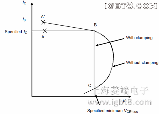
In a preliminary test, the action of the clamping unit should be verified by decreasing its adjustable voltage V2; then the clamping unit should be adjusted to the desired value of VCE that corresponds to the specified current IC (point B of Figure 12).转载请注明出处:http://www.igbt8.com/
6.3.1.6 要求
– The IGBT is satisfactory when the trace moving from point B to point C does not pass to the left of the line BC.
– When the clamping unit is not used, the IGBT is satisfactory if the trace effectively turns around point B, as shown in Figure 12.
6.3.1.7 规定条件
– Case or ambient or virtual junction temperature Tc or Ta or Tvj:环境温度、壳温、结温。
– Collector current IC:集电极电流IC
– Minimum sustaining voltage VCERsus, VCESsus:最小维持电压VCERsus
– Value of load inductance L, where appropriate:合适的负载电感
– Value of unclamped stray inductance Ls:未钳位杂散电感
– Frequency of the gate voltage pulse generator VG, if different from 50 Hz:门极电压脉冲发生器频率。
– Gate resistor R1, R2, if available:若需要,门极电阻R1,R2
– Gate voltage VGG1 and VGG2 (shall be specified):门极电压VGG1及VGG2
6.3.1.1 目的
The purpose is to ensure that the collector-emitter sustaining voltage of an IGBT is not less than the maximum specified value VCE*sus under specified conditions.文章来源:http://www.igbt8.com/jc/172.html
6.3.1.2 测试电路 (see Figure 11)
Figure 11 – Circuit for measuring the collector-emitter sustaining voltage VCE*sus
6.3.1.3 电路描述及要求The IGBT is operated in a saturated condition under pulse operation.
Due to the inductance L, switching off the gate voltage causes the IGBT to be swept through a current-voltage cycle.
The voltage source VCC1 is adjustable; it enables the collector current to be set to the specified value.
A voltage clamping unit, indicated in Figure 11 as a variable voltage source VCC2 in series with a diode, limits the voltage VCE. VCC2 is set to the expected value of VCE*sus.
The minimum value of load inductance L may be given in the detail specification; otherwise, it may be calculated from
Lmin = (VCC2 – VCC1) * toff / 0,1 IC
This ensures that IC does not drop by more than 10% during toff.
6.3.1.4 测试流程
The clamping unit is adjusted to operate at the specified minimum value VCE*sus. With voltage VCC1 set at zero, VGE is adjusted so that the specified current IC can be reached with a VCE value in the saturated condition (point A in Figure 12).
The value VCC1 is progressively increased until the specified current IC is reached for the expected VCE*sus (point B in Figure 12). As a result, the current at which the cycle starts may reach a value I0 slightly higher than the specified current IC (point A′ of Figure 12).
Specified IC
Figure 12 – Operating locus of the collector current
6.3.1.5 注意事项In a preliminary test, the action of the clamping unit should be verified by decreasing its adjustable voltage V2; then the clamping unit should be adjusted to the desired value of VCE that corresponds to the specified current IC (point B of Figure 12).转载请注明出处:http://www.igbt8.com/
6.3.1.6 要求
– The IGBT is satisfactory when the trace moving from point B to point C does not pass to the left of the line BC.
– When the clamping unit is not used, the IGBT is satisfactory if the trace effectively turns around point B, as shown in Figure 12.
6.3.1.7 规定条件
– Case or ambient or virtual junction temperature Tc or Ta or Tvj:环境温度、壳温、结温。
– Collector current IC:集电极电流IC
– Minimum sustaining voltage VCERsus, VCESsus:最小维持电压VCERsus
– Value of load inductance L, where appropriate:合适的负载电感
– Value of unclamped stray inductance Ls:未钳位杂散电感
– Frequency of the gate voltage pulse generator VG, if different from 50 Hz:门极电压脉冲发生器频率。
– Gate resistor R1, R2, if available:若需要,门极电阻R1,R2
– Gate voltage VGG1 and VGG2 (shall be specified):门极电压VGG1及VGG2
服务热线:021-58979561
业务咨询qq:447495955
业务咨询qq:1852433657
业务咨询qq:513845646
技术支持qq:313548578
技术交流群:376450741
业务咨询:
业务咨询:
业务咨询:
技术支持:
媒体合作:
沪ICP备09068927号 igbt8.com版权所有 Copyright 2008-2018
URL:http://www.igbt8.com qq:1852433657 欢迎加入IGBT技术交流群:376450741
技术支持: IGBT应用技术网
URL:http://www.igbt8.com qq:1852433657 欢迎加入IGBT技术交流群:376450741
技术支持: IGBT应用技术网