热销产品
NTC温度传感器测量IGBT模块温度(2)
2 应用NTC进行温度测量
NTC安装在IGBT模块的DCB上,在模块内的热量流通如下图描述。
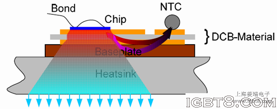
Flow of thermal energy inside a power electronic module
芯片产生的热量大部分直接流到散热器然后从散热器散发到环境中。此外,热流量通过DCB材料及基板流向NTC的位置。因为热量不能瞬间流动,NTC只适用于表征稳定工作状态下的IGBT模块外壳温度。瞬态现象如短路条件下产生的热量不能通过NTC监测,因为相关的时间常数太小,因此,NTC不能用于IGBT短路保护!文章来源:http://www.igbt8.com/sr/169.html
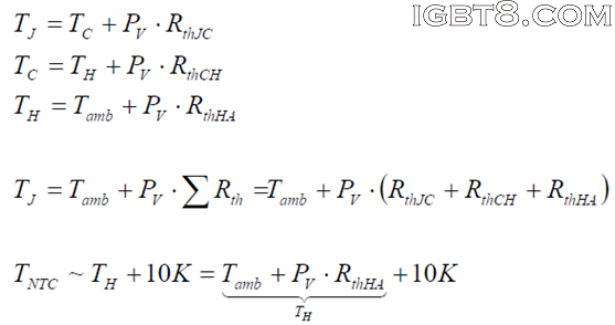
表示热量流通路径的等效电路如下图所示:

Equivalent thermal schematic
From this overview, two conclusions can be drawn:1. As there is a temperature drop along the path RthJNTC connecting the chip’s junction to the NTC, the thermistor’s temperature TNTC has to be lower than the junction temperature TJunction.
2. For the same reason, the temperature of the NTC has to be higher than the temperature that can be detected at the heatsink.
From experience, the difference between the heat sink’s temperature and the NTC’s temperature is about 10K at temperature levels common for power electronic devices.
Knowing the proper values for the Rth-chain is mandatory if temperatures that cannot be measured directly are calculated from these values. For a given module, the according values for RthJC and RthCH can be read from the datasheet for both the IGBT as well as for the diode.转载请注明出处:http://www.igbt8.com/
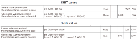
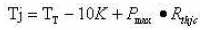
With these values the thermal situation now can be calculated

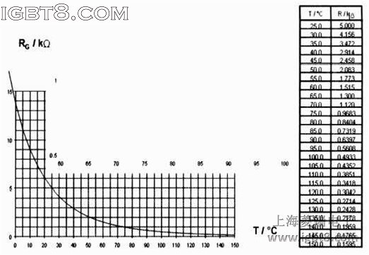
NTC电阻-温度曲线图
温度传感器的时间常数是2秒,由于芯片热时间常数非常小,而整个散热系统的时间常数又非常大,因此,NTC检测到的温变是时间比较长的过载情况。上图以曲线的形式显示了温度与电阻值的关系,也可以使用下面的解析函数来描述曲线:
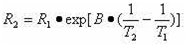
T2是检测温度(开氏温标),R2在T2温度时NTC的阻值。
服务热线:021-58979561
业务咨询qq:447495955
业务咨询qq:1852433657
业务咨询qq:513845646
技术支持qq:313548578
技术交流群:376450741
业务咨询:
业务咨询:
业务咨询:
技术支持:
媒体合作:
沪ICP备09068927号 igbt8.com版权所有 Copyright 2008-2018
URL:http://www.igbt8.com qq:1852433657 欢迎加入IGBT技术交流群:376450741
技术支持: IGBT应用技术网
URL:http://www.igbt8.com qq:1852433657 欢迎加入IGBT技术交流群:376450741
技术支持: IGBT应用技术网